Machinable Materials
|
Category
|
Grades
|
|
Aluminum
|
AL6061, AL6063, 7075, 2017
|
|
Stainless Steel
|
SUS303, SUS304, SUS316
|
|
Non-Metals
|
PEEK, POM, Nylon, PC, ABS, Acrylic
|
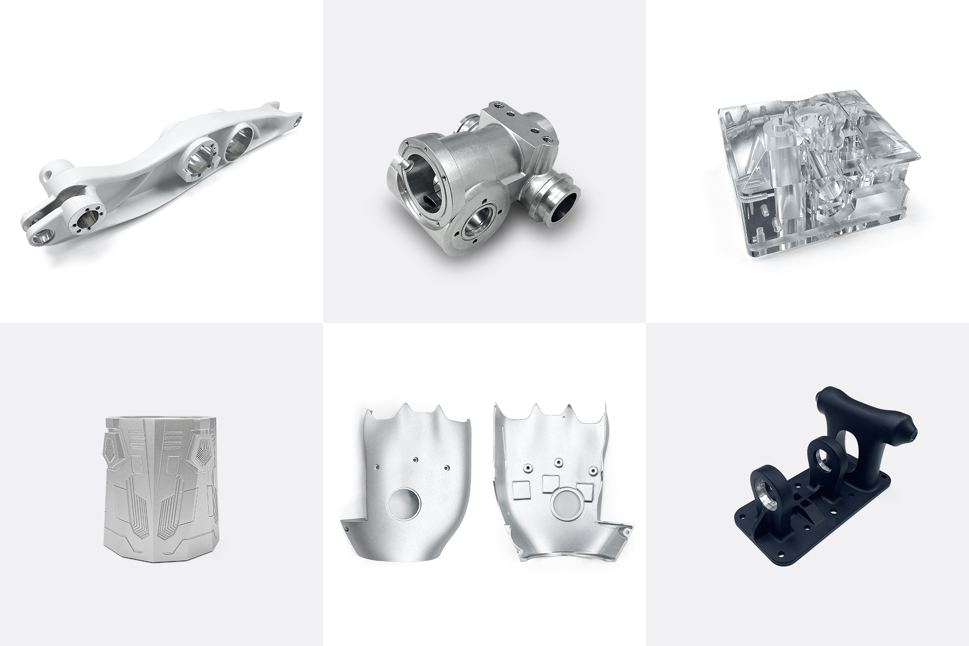
5-Axis CNC Machining – Selection Criteria
When to Choose 5-Axis Machining
5-axis machining is the lower-risk, more predictable option when any of the following conditions apply:
|
Trigger Condition
|
Dewspiption
|
|
Multi-sided critical features
|
Machining features distributed across ≥3 faces, with angled holes, mounting surfaces, and interfaces that must align to the same datum
|
|
Limited tool accessibility
|
Deep cavities (depth-to-diameter ratio ≥5:1), compound angles, or negative draft angles that standard tools cannot reach
|
|
CTQ features across multiple faces
|
Critical-to-Quality (CTQ) dimensions span multiple faces and require single-setup positioning
|
|
Freeform surfaces / impellers
|
Complex curved surfaces typical in aerospace and medical applications
|
|
Thin-wall structures
|
Wall thickness ≤1.5 mm, requiring controlled cutting force direction to avoid deformation
|
When NOT to Choose 5-Axis Machining
5-axis is not always the optimal solution:
|
Scenario
|
Recommended Process
|
Justification
|
|
Simple prismatic plate parts
|
3-axis milling
|
Simpler programming, lower machine hourly rate, easier inspection
|
|
Standard brackets / shaft parts
|
3-axis or Swiss-type turning
|
More economical for high-volume production, better concentricity control
|
|
CTQ features on one face only
|
3-axis or 3+2 positioning
|
Multi-face datum control provides limited benefit
|
|
No undercuts / no compound angles
|
3-axis
|
Full 5-axis adds programming and fixturing complexity without reducing setups
|
Principle: Geometry drives process selection – do not use 5-axis for the sake of using 5-axis.
5-Axis vs. 3-Axis / Turning – Decision Matrix
|
Consideration
|
5-Axis Machining
|
3-Axis Milling / Swiss-Type Turning
|
|
Applicable geometry
|
Multi-sided, compound angles, freeform surfaces, deep cavities
|
Prismatic, 2.5D features, slender cylindrical parts
|
|
Number of setups
|
1
|
≥2
|
|
Tolerance risk
|
No stack-up error
|
Tolerance accumulation from multiple re-fixturing
|
|
Programming complexity
|
Higher
|
Lower
|
|
Hourly rate
|
Higher
|
Lower
|
|
Optimal batch size
|
Low to medium volume
|
High volume (≥500 parts/batch)
|
|
Typical parts
|
Impellers, housings, optical mounts
|
Plates, brackets, shaft parts
|
5-Axis Machining – Tolerance Capability & Verifications
General Tolerance vs CTQ Tolerance
|
Type
|
Dewspiption
|
|
General features
|
Per drawing standards or ISO 2768-m (medium tolerance)
|
|
CTQ critical dimensions
|
Requires feature-by-feature review – cannot assume uniform tolerance across the entire part. Hole position, flatness, profile, sealing surfaces, and compound angles each require different fixturing strategies, tooling approaches, and inspection methods.
|
Principle: CTQ tolerance capability is determined by feature type, not by the machine itself.
Factors Affecting Achievable Tolerance
Achievable tolerance depends not only on the 5-axis machine but also on the following factors:
|
Factor
|
Dewspiption
|
|
Material stability
|
High-performance aluminum alloys such as 7075-T6 may experience deformation from stress relief
|
|
Part geometry / wall thickness
|
Thin-wall structures (≤1.5 mm) require controlled cutting force direction
|
|
Tool accessibility
|
Features with high length-to-diameter ratio are prone to chatter, affecting accuracy
|
|
Datum transfer
|
Drawing datum must align with fixturing direction
|
|
Inspection method
|
CMM measurement strategy, probe compensation, and temperature compensation all affect results
|
Engineering review requirement: For thin-wall parts, deep cavities, and high length-to-diameter ratio features, the ability to maintain target tolerances from prototype to production must be verified before sampling.
Datum, Fixturing & Inspection Planning
Strict tolerances begin with the datum system – not the machine itself. Our review process is as follows:
1.Datum alignment:Compare drawing datum against fixturing direction, tool accessibility, and clamping logic
2. Strategy confirmation:Reduce re-fixturing error and improve feature consistency
3. Inspection validation:Provide verification plan for confirmed CTQ dimensions
5-Axis Machining – Material Capabilities & Process Considerations
Machinable Materials Overview
|
Category
|
Typical Applications
|
|
Aluminum (AL6061, AL6063, 7075, 2017)
|
Lightweight structural parts, housings, frames
|
|
Stainless Steel (SUS303, SUS304, SUS316)
|
Medical components, corrosion-resistant parts, structural parts
|
|
Non-Metals (PEEK, POM, Nylon, PC, ABS, Acrylic)
|
Insulators, chemical-resistant parts, lightweight alternatives
|
Material-Specific Process Tips
Aluminum (AL6061 / AL6063 / 7075 / 2017)
|
Aspect
|
Recommendation
|
|
Processing risk
|
Thin-wall structures (≤1.5 mm) require staged roughing and finishing to reduce deformation caused by stress relief
|
|
Inspection tip
|
Verify that residual stress has been fully relieved before final inspection to avoid measurement errors from part distortion
|
Stainless Steel (SUS303 / SUS304 / SUS316)
|
Aspect
|
Recommendation
|
|
Processing risk
|
High cutting forces require rigid fixturing; thin-wall or slender features are prone to tool deflection
|
|
Inspection tip
|
CMM touch-trigger inspection recommended – avoid excessive measurement force that may cause elastic deformation
|
Non-Metals (PEEK / POM / Nylon / PC / ABS / Acrylic)
|
Aspect
|
Recommendation
|
|
Processing risk
|
Control clamping force (prevent indentations), maintain sharp tools (prevent melting/burrs), manage heat buildup
|
|
Inspection tip
|
Use conservative finishing parameters; reduce clamping pressure during inspection to prevent post-machining deformation from affecting measurements
|
Material-Related Risks – DFM Review Items
Before quoting or sampling, we screen for the following material-related risks:
|
Risk Category
|
Items Reviewed
|
|
Raw material condition
|
Grain direction, internal stress, stock allowance
|
|
Machining deformation
|
Stress relief after roughing, unsupported thin-wall features
|
|
Fixturing response
|
Clamping deformation on soft materials, insufficient support for thin-wall parts
|
|
Inspection consistency
|
Post-machining springback, temperature effects on measurement results
|
Countermeasures (proposed before production when necessary):
● Adjust datum strategy
● Increase stock allowance
● Add support surfaces
● Modify machining sequence (separate roughing and finishing)
3+2 Positioning vs. Full 5-Axis – Strategy Selection Guide
One-Sentence Rule
3+2 positioning:Multi-sided prismatic parts (angled holes, ports, cavities, sealing surfaces)
Full 5-axis simultaneous:Freeform surfaces (impellers, flow channels, organic shapes)
Principle: Not every 5-axis part requires continuous motion. Strategy is determined by geometry – whether the part requires multi-sided positional relationships or continuously changing tool orientation for curved surfaces.
Strategy Comparison
|
Consideration
|
3+2 Positioning
|
Full 5-Axis Simultaneous
|
|
Applicable geometry
|
Multi-sided prismatic parts, angled holes, cavities, sealing surfaces
|
Impellers, blade-like features, complex flow channels, organic surfaces
|
|
Motion mode
|
Rotary axes lock after positioning; cutting performed in 3-axis mode
|
Continuous tool vector changes during cutting
|
|
Rigidity
|
Higher (rotary axes locked)
|
Lower (axes in continuous motion)
|
|
Programming complexity
|
Lower
|
Higher
|
|
Inspection difficulty
|
Easier (fixed angles simplify CMM programming)
|
More complex (requires surface matching strategy)
|
|
Typical parts
|
Multi-sided housings, valve bodies, optical mounts
|
Impellers, artificial joints, complex flow channels
|
Impact on Cost, Cycle Time & Inspection
|
Aspect
|
3+2 Positioning
|
Full 5-Axis Simultaneous
|
|
Programming time
|
Shorter
|
Longer
|
|
Cycle time
|
Typically shorter (higher rigidity allows aggressive parameters)
|
Potentially longer (requires dynamic accuracy control)
|
|
Number of setups
|
1 (but requires positioning at multiple angles)
|
1 (continuous curved surface machining)
|
|
Inspection complexity
|
Low (fixed angles, easy CMM programming)
|
High (requires surface matching strategy)
|
|
Cost
|
Lower (lower hourly rate, faster programming)
|
Higher (longer programming + validation time)
|
5-Axis CNC Machining – Cost Drivers & DFM Review
The Cost Logic of 5-Axis Machining
Total cost of 5-axis machining = Higher machine hourly rate vs. Savings from process integration
For complex parts, the higher spindle hour cost of 5-axis machining is typically offset by savings in the following areas:
|
Savings Source
|
Dewspiption
|
|
Non-productive labor
|
Reduced time for multiple setups, re-fixturing, and part alignment
|
|
Custom fixture manufacturing
|
No need to design dedicated fixtures for each face
|
|
Datum transfer risk
|
Single setup avoids scrap caused by tolerance stack-up
|
Core advantage: Complete all machining in one setup – eliminate the inherent "tolerance stack-up" of multiple re-fixturing operations.
Four Key Factors That Drive Cost
Before quoting, we evaluate the following four drivers to provide an engineering-based, accurate quote:
|
Factor
|
Impact Dewspiption
|
|
Raw material
|
High-performance aluminum alloys (e.g., 7075) have higher material cost and impact tool life
|
|
Fixturing complexity
|
Complex toolpaths require advanced CAM programming and collision simulation, increasing upfront engineering investment
|
|
Tolerance range
|
Tight CTQ tolerances (e.g., ±0.005 mm) require slower feeds and more control cycles
|
|
Inspection scope
|
Complex CMM cycles + FAI documentation add time beyond spindle machining
|
How to Get a More Accurate Quote
To provide an executable fixed-price quote, please provide:
|
Required File
|
Purpose
|
|
STEP file
|
Geometry analysis
|
|
2D drawing (with GD&T)
|
Identify CTQ dimensions and inspection requirements
|
DFM Review – What We Check Before Machining
We identify risks in three areas – geometry, fixturing, and inspection – before production.
Tool Accessibility & Overhang
|
Check Item
|
Dewspiption
|
|
Deep cavities / angled ports
|
Verify stable tool access – avoid excessive overhang or holder interference
|
|
Impact
|
Directly affects toolpath stability and achievable tolerances
|
Wall Thickness & Stability
|
Check Item
|
Dewspiption
|
|
Thin-wall features
|
Identify areas prone to vibration or tool deflection
|
|
Geometric transitions
|
Review against material properties (e.g., 7075 brittleness, PEEK thermal sensitivity) before quoting
|
Datum Logic & Inspection
|
Check Item
|
Dewspiption
|
|
Datum alignment
|
Drawing datum system alignment with planned fixturing direction
|
|
Purpose
|
Reduce datum transfer error and improve CTQ verification consistency
|
Proactive Feedback – Reducing Risk & Cost
We return engineering feedback within 24 hours of your inquiry, including:
Suggested geometric adjustments (simplify machining, shorten cycle time)
Fixturing strategy optimization
Inspection strategy confirmation
Purpose: Align the quote with realistic machining strategies and inspection scope – avoid rework, unstable quoting assumptions, and post-production design changes.
DFM Review Output Checklist
|
Output Item
|
Content
|
|
Tool accessibility assessment
|
Overhang length, interference risk, achievable tolerance estimate
|
|
Thin-wall stability annotation
|
High-risk areas and process recommendations (e.g., staged roughing/finishing)
|
|
Datum strategy confirmation
|
Alignment of fixturing direction with drawing datum
|
|
Inspection plan
|
CMM strategy, FAI scope, bubble drawing requirements
|
|
Design change recommendations
|
If applicable (simplify features, add support surfaces, etc.)
|
Industries Where 5-Axis Verification Is Critical
Medical
|
Item
|
Dewspiption
|
|
Applicable materials
|
Stainless steel: SUS303 / SUS304 / SUS316; Non-metal: PEEK
|
|
Typical parts
|
Surgical instruments, housings, implant-related components
|
|
Verification focus
|
Material traceability, feature-level inspection, functional surface condition
|
|
Documentation scope
|
Per project requirements – ensures compliance with regulatory and engineering specifications
|
Robotics
|
Item
|
Dewspiption
|
|
Applicable materials
|
Aluminum: AL6061
|
|
Typical parts
|
Joints, sensor housings, connectors
|
|
Verification focus
|
Positional repeatability, controlled concentricity, mating feature alignment
|
|
Design requirements
|
Balance of rigidity, weight, and assembly fit
|
UAV / Drone
|
Item
|
Dewspiption
|
|
Applicable materials
|
Aluminum: 6061-T6, 7075-T6; Non-metal: ABS
|
|
Typical parts
|
Arm connectors, motor mounts, airframe frames, gimbal brackets, sensor housings
|
|
Verification focus
|
Multi-face datum alignment, thin-wall deformation control, fit accuracy, lightweight structure integrity
|
|
Inspection scope
|
Full CMM or critical dimension inspection + FAI report + bubble drawing
|
Process notes:
Thin-wall structures (≤1.5 mm) require staged roughing and finishing
CTQ tolerances on mating faces must be called out in advance
If anodizing is required, allow stock and specify in advance