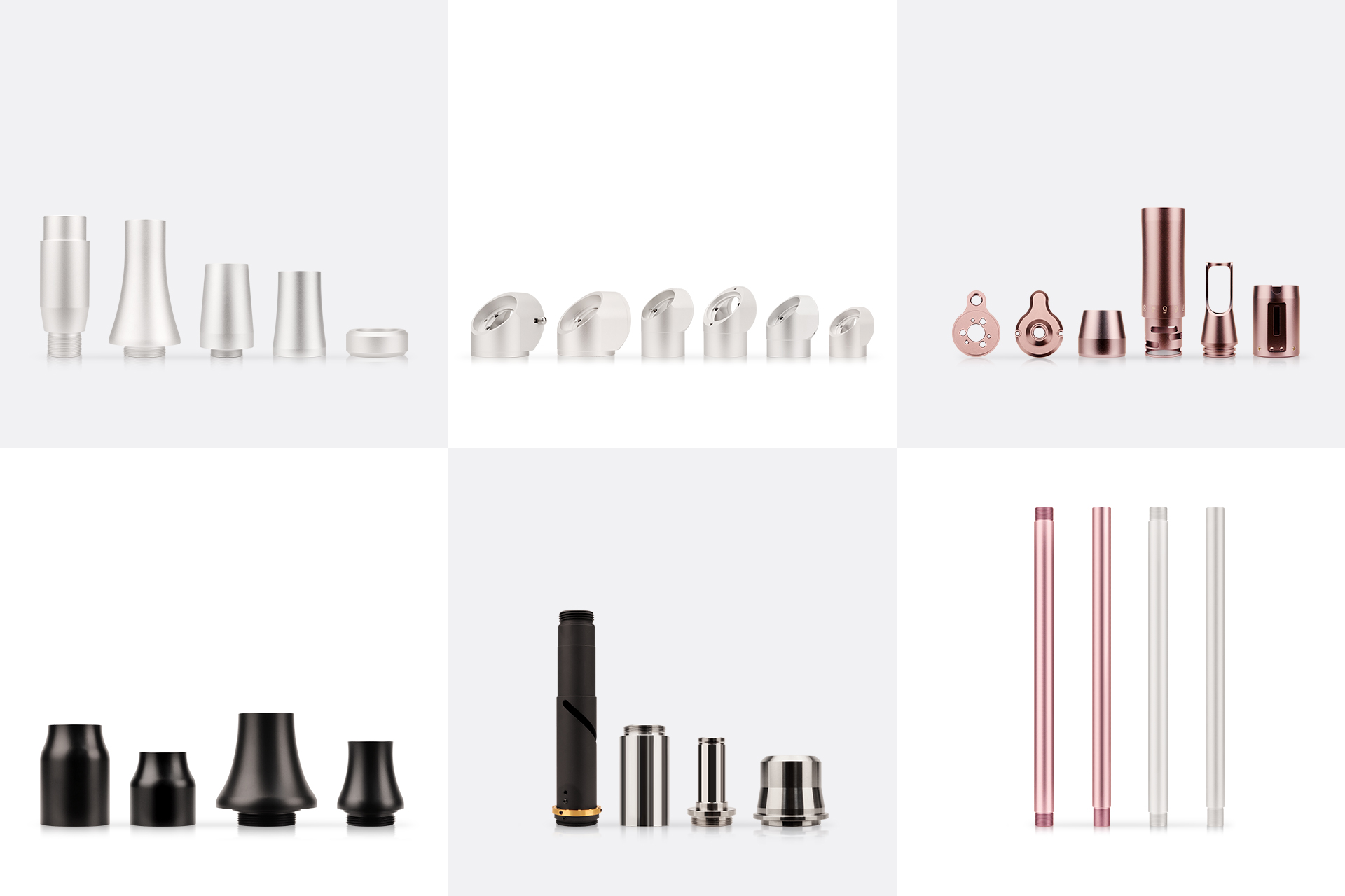
4-Axis CNC Machining – Efficient Solution for Multi-Sided Parts & Cylindrical Features
4-axis CNC machining adds a rotary axis (typically the A-axis, rotating around the X-axis) to standard 3-axis (X, Y, Z) capabilities, significantly expanding machining capability without excessive cost. Its core value is "complete multi-sided machining in one setup" , reducing re-fixturing, minimizing positional error accumulation, improving feature-to-feature consistency, and simplifying fixture design.
Typical 4-Axis Parts
4-axis machining is suitable for cylindrical parts, helical features, and multi-sided structures. Typical examples include:
|
Part Category
|
Typical Examples
|
Machining Characteristics
|
|
Cylindrical Parts
|
Drive shafts, hydraulic cylinders, flanges
|
Complete OD, ID, keyways, threads in one setup
|
|
Helical Parts
|
Screw shafts, spiral conveyors, thread mills
|
Continuous helical interpolation with 4-axis simultaneous
|
|
Multi-Sided Parts
|
Engine blocks, machine brackets, multi-sided connectors
|
Reduced setups for drilling, milling, tapping
|
|
Eccentric/Cam Parts
|
Camshafts, eccentric wheels, eccentric bushings
|
Precision machining of eccentric features via rotary axis
|
|
Gear Parts
|
Spur gears, helical gears, worm gears
|
High-accuracy gear cutting with 4-axis simultaneous
|
|
Complex/Contoured Parts
|
Custom brackets, complex connectors, mold textures
|
Flexible angle positioning via rotary axis
|
3+1 Positional vs. Full 4-Axis Simultaneous – Strategy Selection
4-axis machining includes two core strategies for different applications. Process selection should be driven by part geometry, not by pursuing full simultaneous capability.
3+1 Positional Machining
The 4th axis rotates the workpiece to a fixed angle and locks. Standard 3-axis machining is then performed at that angle. The rotary axis is used only for indexing and positioning, not during cutting.
● Best for: Multi-sided prismatic parts; parts requiring machining (drilling, tapping, facing) on multiple faces
● Advantages: Reduces machining time by 30-50% compared to 3-axis; simple programming; rigid and stable; ideal for production runs
● Typical applications: Valve body machining, roughing of shaft parts, deep cavity structures
Full 4-Axis Simultaneous Machining
X, Y, Z linear axes and the A rotary axis move simultaneously, enabling continuous curved surface cutting.
● Best for: Parts with contoured surfaces (e.g., helical grooves, cam surfaces, impeller blades, 3D carving)
● Advantages: No tool mark steps; smooth, continuous surfaces; true flank cutting and envelope machining
● Typical applications: Turbine blades, artistic reliefs, fine mold cavity machining
Selection Tip: Use 3+1 positional machining for holes, slots, and flat surfaces distributed across multiple planes – it is more stable and efficient. Use full 4-axis simultaneous for continuously varying curved surfaces around the circumference (e.g., helical grooves, cam contours).
Tolerance Capability
4-axis CNC machining achieves high precision:
|
Type
|
Tolerance
|
|
Standard positional accuracy
|
±0.01 mm
|
|
Critical features (concentricity, position tolerance)
|
±0.005 mm (under high-precision requirements)
|
Note: Achievable precision depends on machine rigidity, tool condition, setup stability, and part geometric complexity. Review by feature type is required before production.
Machinable Materials
4-axis CNC machining covers the following material range:
|
Category
|
Grades
|
Typical Applications
|
|
Aluminum
|
AL6061, AL6063, 7075, 2017
|
Structural parts and heat sinks for robotics, UAVs, and electronics
|
|
Stainless Steel
|
SUS303, SUS304, SUS316
|
Multi-angle components for medical, automation, and marine applications
|
|
Non-Metals
|
PEEK, POM, Nylon, PC, ABS, Acrylic
|
Components for medical, electronics, and consumer goods
|
|
Copper & Brass
|
—
|
Electrical and fluid system components
|
Cost Drivers
4-axis machining cost is determined by machine hourly rate, setup & programming investment, and inspection complexity – not simply by machining time.
Core Cost Components
|
Factor
|
Dewspiption
|
|
Setup & Fixturing Cost
|
4-axis covers multiple faces in one setup, significantly reducing design and manufacturing costs for dedicated flip fixtures
|
|
Programming Complexity
|
4-axis toolpath planning (especially simultaneous paths) requires advanced CAM programming and collision simulation, increasing initial engineering investment
|
|
Cycle Time
|
Reduced setups and manual intervention significantly shorten total machining time, offsetting higher hourly rates
|
|
CMM Inspection
|
GD&T measurement of multi-sided features requires longer CMM verification time. CTQ scope and inspection frequency should be agreed upon during quoting
|
Cost Control Recommendations
● Use 3+1 positional machining rather than full simultaneous whenever possible – controls cost and programming difficulty while meeting multi-sided requirements
● Provide STEP models and CTQ-callout drawings early – enables supplier to evaluate fixturing strategy and inspection scope during DFM
● Avoid overly tight tolerances on non-critical features – reduces inspection cycle time and tool control cost
Design for Manufacturability (DFM) Review
The DFM review prior to 4-axis machining focuses on the following areas:
Setup & Datum Strategy
● Verify that the part datum aligns with the 4-axis rotary center to eliminate coordinate shift after rotation
● Confirm that the fixturing strategy allows all target faces to be machined in one setup, avoiding tolerance stack-up from re-fixturing
● Evaluate fixture design to ensure no interference during rotation
Tool Accessibility & Wall Stability
● Inspect tool accessibility for deep cavities, helical grooves, or compound angle features – avoid chatter and tolerance drift caused by excessive tool overhang
● Identify thin-wall features and high material removal rate areas – assess deformation risk and recommend staged roughing and finishing strategies
● Review cutting parameters and cooling strategies for rotary machining based on material properties to prevent thermal deformation
Design Recommendations & Risk Feedback
● Proactively suggest geometric adjustments before quoting to simplify fixturing and shorten cycle time
● Flag potential interference or over-travel issues (e.g., A-axis exceeding ±180°) in advance – recommend feature angle adjustments or fixturing direction changes
● Ensure the final quote covers realistic machining strategies and inspection scope by reviewing datum strategy and CTQ features in advance